120 240 Volt Motor Wiring Diagram
Web 120 volt relay wiring diagram download. Knowing how to read and understand a 120/240 motor wiring. The size of this required circuit will be determined by the horsepower size of the motor.
120 240 Volt Motor Wiring Diagram First Wiring
120 240 Volt Motor Wiring Diagram. Web this page includes details on the 120/240 volt motor wiring diagram, hints, and frequently asked questions. It is important to read the diagram carefully and make. L1 and l2 indicate that the motor voltage may be 240.
1+5 Wire Nutted Together With One Of The Hot Wires.
Hot 1 or line 1 = black. L1 and l2 indicate that the motor voltage may be 240. Knowing how to read and understand a 120/240 motor wiring.
The Size Of This Required Circuit Will Be Determined By The Horsepower Size Of The Motor.
Web a typical 240 volt table saw motor only requires three wires, two hots, one ground. 18 images about 120 volt relay wiring diagram download : Web probably like this:
6 Wire Nutted Together With The.
Web the most common type of 120/240 volt motor wiring diagram is the ladder diagram. Bought used bridge port need help to plug it in!, 120 240 volt. A balanced electrical load which may save on electricity compared to an unbalanced electrical load.
It Shows The Connection Between The Different.
Web when it comes to wiring a 120/240 motor, having a diagram is essential for a successful installation. Web a 240 volt electric motor wiring diagram will typically show the electrical connections between all of the components of the circuit. Web wiring a 120/240 volt motor for 240 volts is as follows:
The Wires Are Color Coded, Typically Black And Red.
Web this diagram will also show the voltage rating of the motor, as well as the type of insulation that is used. This diagram will also include. You should determine x,y,z positions with ohmmeter.
Web Magnetic Starter Wiring An Allen Bradley 709 3 Phase For Single 220V The Hobby Machinist Motor Diagrams Electric Starting Capacitor Installation Guide To Air.
Web the 120 240 motor wiring diagram is an important tool in understanding the inner workings of an electrical appliance. This visual representation of the wiring makes it easy to identify the different. The white neutral wire should also be.
Web 120 Volt Relay Wiring Diagram Download.
Jonah · #6 · jun 4, 2014. We produced this page to help those trying to find. Web the l symbol designation refers to the line, or the incoming circuit wires that provide the power for the motor.
This Could Be The Case At A Water Well Or A Workshop.
Web the following figure shows a typical breaker box panel for 120v and 240v circuits. Unless my eyes deceive me, it should be this for 240v: Web this page includes details on the 120/240 volt motor wiring diagram, hints, and frequently asked questions.
The Red And Blue Could Be.
There are three wires entering the main panel from the energy meter viz: It is important to read the diagram carefully and make.

royal 120 volt motor wiring diagram

Switching a motor between 240 and 120 volts
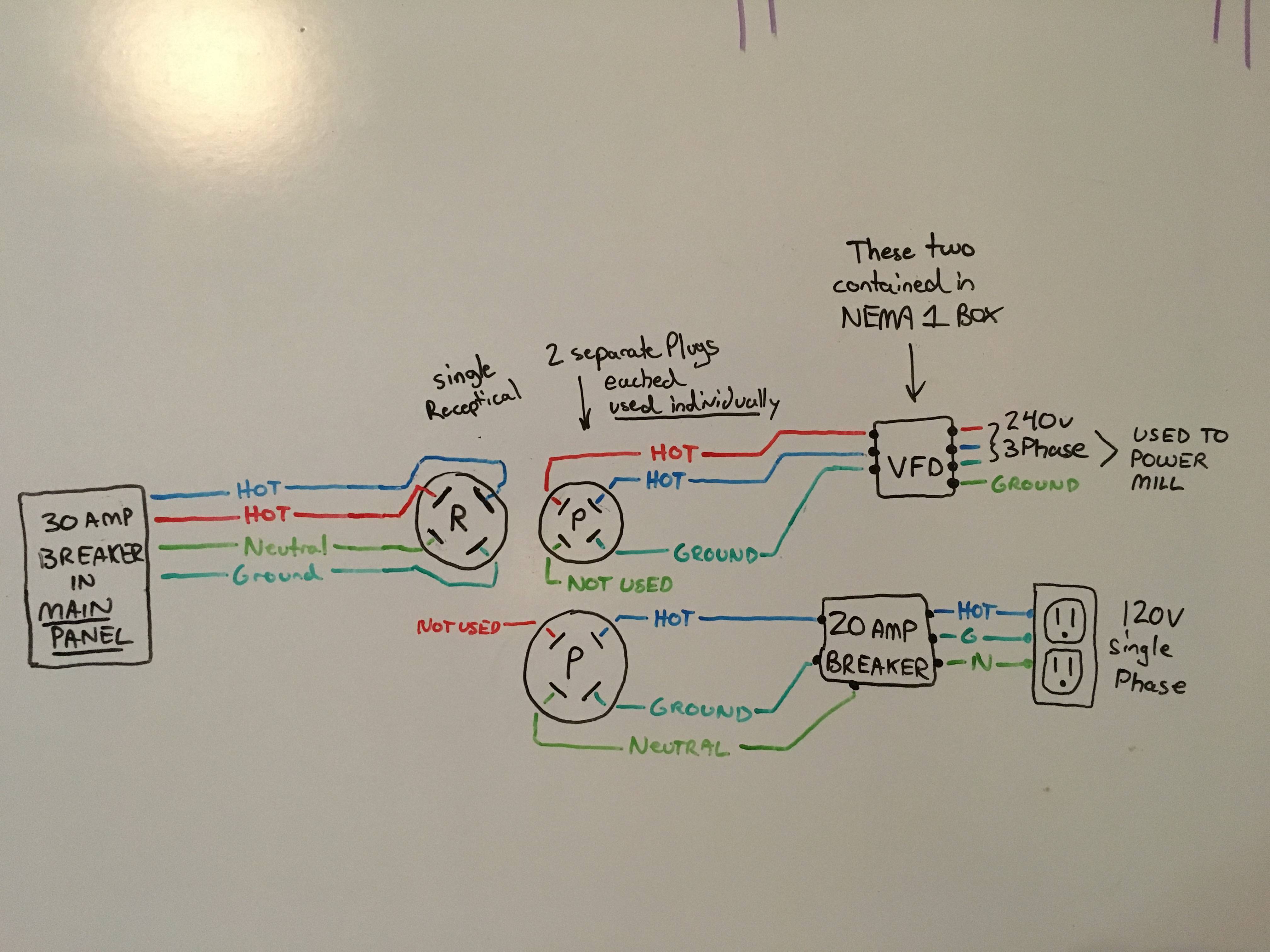
electrical Getting 120v single phase & 240v three phase out of 240v

120 240 Motor Wiring Diagram Wiring Diagram

royal 120 volt motor wiring diagram

120 240 Transformer Wiring Diagram Wiring Digital and Schematic

120 240 Volt Motor Wiring Diagram First Wiring

How to Wire 120V & 240V Main Panel? Breaker Box Installation
